- 1. First Steps
- 2. Calculations and Model Construction
- 3. Construction of the Main Parts
- 4. First Experiences and Improvements
- 5. Completion
1. First Steps
a) Hull Shape
The most important aspect of the blimp Simon was its overall design
and the dimensions of its envelope. Because the actual size could not be
evaluated before the weight of the structure was known, a first design
only included the form and ratio of the hull and not its final dimensions.
Two aspects were important when designing the front or tail piece of the
blimp. There was the look of a zeppelin, an aerodynamically formed nose
and a tail possibly pointed or round. Also, there was the volume to surface
ratio affecting air resistance, wind influences and most important, cost.
Simon took a special approach to a design of an ellipsoid of revolution
(EoR), giving it the look of a blimp. Different length to width ratios
were drawn and their volume graphs had to be calculated to be able to compare
the advantages of each design (done with the mathematical computer program Maple V).
A ratio of 1 : 3.27 was finally chosen. The advantages are a large volume
even for small radii and thus a large lifting force and low air resistance.
At the same time, the ratio looked good.
In the same way, a middle cylinder (MC) was fitted into the system. Its
length was determined to be two thirds of the length of half the ellipsoid.
b) A Gondola
The gondola design proved to be quite hard. Since computer models were
not satisfying, the form of the gondola was developed by hand, simply by
drawing various sketches. The result was a drop-like, aerodynamic shape.
A size of 0.60m x 0.28m x 0.10m was chosen because of considerations including
the size of the accumulators, a width supporting the tilting axle and the
weight of the motors and propellers, and space for the electronics. The
axle would be at the largest width of the gondola. The material to be used
is GFC, light and tough.
c) Dimensions
It finally got time to set Simon's actual size. Thus, the electronics,
a servo, two motors, two speed controllers, a receiver, and 16 accumulators
were bought and weighted. Mylar foil was also weighted, together with the
balsa wood needed for the stabilizers.
It can be said, that the dimensions of an airship depend on the power
output of its motors, since the motors and accumulators make up for the
largest part of its weight. The more power the motors produce and the more
accumulators are needed, the bigger the airship gets.
The volume to radius ratio, and thus also the lifting force for a given
radius of Simon had previously been evaluated. Because motor power output
- and the weight of the motors - also depend on the size and volume of
an airship, the following relation between fg and flift
was drawn as shown in the graph below. Since Simon was meant to be an outdoor
blimp, fighting against wind and turbulences, it had to be motorized sufficiently,
meaning a quite large motor weight. Not expressed in the graph are the
influences of inertia and other more complicated aspects, since the graph
itself is only an approximation.
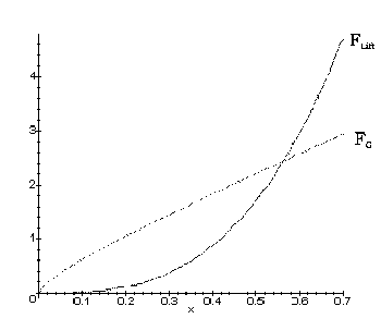
From the graph , the minimum dimensions of Simon could be determined. they
lay around a radius of 0.5 m and thus an overall length of 4.3 m. As previously
mentioned in General Airship Design, 110 percent of these values were used for Simon to
take precautions against any eventualities. See Simon's
dimensions.
2. Calculations and Model
Construction
a) Hull Values
It is always best to find out the main data of an airship, to see where
possible problems might come up. Is flift large enough? How
large is the surface of the blimp? etc.
The exact volume of Simon had been calculated by formula (3) and (4) already
mentioned in General Airship Design. The origin
of (3) derives from the equation of an ellipsoid, (6) and (7).
 (6)
(6)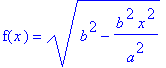 (7)
(7)The formula for any body of revolution and thus also for
Simon's EoR is expressed through
 (8)
(8)When substituting (7) for f(x) one gets the final formula
for an EoR
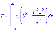 (9)
(9)When formulas (3) and (4) are evaluated, the volume of
the ellipsoid and cylinder equal to 3.42 m3.
flift of 100% pure helium (ideal gas) in air at 0°C and 1.013
x 105 Pa is equal to 10.9 N per cubic meter. Using equation (1), a flift
of 37.4 N results. This value may change through pressure and temperature
influence, expressed in equation (10)
 (10)
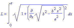
(10)Also, it is important to know the surface of the envelope
to estimate the weight and price of the envelope material needed. It is
given by the equation for the surface of revolution of a body, derived
from the length l of a curve
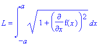 (11)
(11)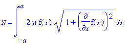 (12)
(12)where, again f(x) is substituted by equation (7). Also,
the equation for the surface of Simon's MC must be considered. it is
The final surface is expressed through
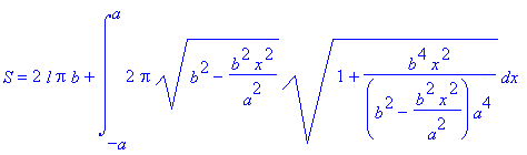 (14)
(14)Simon's surface equals to 14.3m2.
b) Calculating Hullparts
How may one build a threedimensional blimp from plane mylar foil? This
was a central question when building the blimp Simon. Obviously, it could
not be done with one piece, but needed the more, the rounder the structure
had to be. Too many pieces, however, would have made the construction last
forever. Thus, it was decided that Simon would be made of 26 pieces, 12
for the front, 12 for the tail and 2 for the mc. each of them had an additional
glue fold.
The hullparts where obtained by dividing the circumference of the ellipsoid
by 12 at every point x of the x-axis below.
 (15)
(15) (16)
(16)To be able to draw and afterwards actually cut out Simon's
hullparts, the l and w values for a given point x needed to be evaluated.
c) First Models
To control the correctness of the hullpart calculations and see the
gondola in 3D, both, the hull and the gondola, were built as a model first.
From paper, a hull was put together in the actual design of Simon in a
scale of 1:5, and from a polystyrene cylinder, a gondola was cut out true
to scale. It could afterwards be used as a positive form of the real gondola.
A model shows the dimensions in the room. It also helps doublechecking
the theoretical work.
3. Construction of the Main
Parts
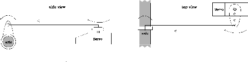
a) a tilting axle
The application of vectored thrust (VT), as already described in General
Airship Design made it necessary to construct a tilting axle. For Simon,
a simple construction as shown below was chosen. VT allows for two different
options. Either only the propellers or both the motors and propellers are
mounted at the tips of the axle. To mount only the propellers rises the
problem of connecting the motors with the propellers through the axle.
To mount the motors and the propellers causes a stability problem: The
axle has to support the weight of the motors and the propellers. It was
decided that Simon would support a system with the motors and propellers
mounted at the tips of the axle; an aluminum pipe (diameter: 8 mm) was
used to overcome stability problems.
b) Construction of the Gondola and the Hull
Since a polystyrene model of the gondola was already made, it was used further to construct the gondola. From the polystyrene shape, a negative form of plaster was cast. After a week the plaster was dry and a layer of wax and one of GFC were laid inside the negative form. the wax kept the plaster from sticking to the GFC. Once the shape of the gondola was finished, holes for the tilting axle were drilled and supporting aluminum braces were glued to the axle and the gondola. The axle was additionally supported by four ball bearings.
Next, the hull had to be put together. Conducting various tests, it was found that contact glue was the ideal adhesive for making the hull heliumtight, since welding was not an option for a polyurethane like mylar. Because the outermost front and tail parts were extremely difficult to glue threedimensionally, a polystyrene body to fit the front and tail of the airship was sanded. It could be used as a 3D surface for gluing. It took 30 to 40 hours of gluing and four tubes of glue to put the envelope together. A valve and two pieces of wood were then placed inside the hull. The valve, with a diameter of 0.01 m, would be used to inflate the blimp, the two pieces of wood to mount the gondola to the hull. The gondola would be coupled to the envelope through four mounting points. Four screws from inside the envelope went through the pieces of wood and attached the gondola to the rest of the airship with wing nuts.
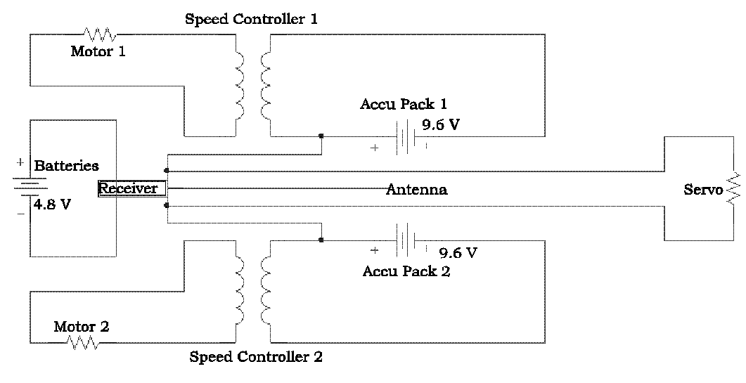
c) The Electronics
Inside the gondola, the electronics needed to properly control the airship were arranged . They included a servo to tilt the motors, sixteen 1.2 V accumulators, two speed controllers, the receiver of the radio-control system and four batteries supplying it with power. Eight accumulators made up an accu pack, connected to each other in series. The receiver controlled the servo and the two motors with their speed controllers. This way, the motors made up two independent circuits.
See a scheme of Simon's electronics.
d) The Fins
At last, tail surfaces were designed. Simon's four fins became huge with a height of 0.55 m each, and a length of 0.40 m, but compared to the envelope, they seemed extremely small.
Made of monokote and light balsa wood, the fins are extremely light. still, they needed to be considered when evaluating the center of gravity of the blimp. The exact center of gravity could only be located empirically, in Simon's case with a large wooden scale.
4. First Experiences and
Improvements
a) Flight Preparations
When all parts were built, they needed to be put together. After connecting
all the electronics inside the gondola and turning the power on, the gondola
could be mounted. Then, the helium was filled in through the valve until Simon
started to float. The fins were attached to the tail by tape. Because of
the extra weight of the fins, more helium was filled in. When Simon floated
again, the helium was substituted by air, filling the envelope all the way,
giving it its final shape and producing a slight overpressure.
b) Flying a blimp
It is no secret now: Simon got too small. Even with little wind, the
airship was shaken by ever little airstream. The problem was not caused
by undermotorization or too small fins. With absolutely no wind Simon obtained
speeds of up to 5 m/s and flew completely steady. Thus, the small airship
Simon involuntarily got only a calm-weather-blimp. One simple measure helped
a little to avoid unpleasant winds: flying at little altitudes!
c) Improvements
After the first practical experiences, many new and sometimes demanding
problems arose. The valve was a little small: With a valve of a larger
diameter, it would not take as long to inflate the blimp. Also, a safety
valve would be preferable. This means some sort of a radio-controlled system
to control the opening of the valve, or even an additional valve. There
were many possibilities to solve the problem, but none of them was easily
applicable. There would be the option of an electromagnetically controlled
valve, a coil with an iron core and an applicable current. A one way version
of a safety valve would be a thin membrane to be destroyed by a movable
and sharp tool such as a needle. Third, there would be the mechanical valve,
controlled by a servo. For Simon none of the above has been used yet, but
the construction and use of a mechanic valve is heavily discussed at this
very moment.
The motors also proved to be difficult to handle. For strong currents,
they were not powerful enough, for calm weather, they were more than sufficient.
Also, during the course of various flights, it was found that the motors
heated up very fast because of a large current flow. It even occurred
once that one of the motors melted out of its fixture! Thus, the use of
other, less resistive motors turning at a lower frequency is discussed
at the moment. The fixture of the motors has already been reinforced by
ring clamps. Also the supporting aluminum braces of the axles have been
reinforced. Previously, they often got damaged during hard landings.
The envelope problem: in the beginning, the hull was amazingly very heliumtight.
But after a few crashlandings and many transportations of the blimp, it
started to leak. The weak points are the vertical glue folds between the
ellipsoid and the cylinder. However, the hull itself got damaged, as well,
and many little holes, invisible for the eye, grew larger. Now test are
being conducted with lacquers such as silicon to seal those holes.
5. Completion
a) Motor Thrust - an Experiment
How powerful are the motors, with the given propellers? The motors
currently used are two Robbe Power Plus 410/12 with two 9-6 propellers.
To experimentally determine the thrust of one of them, a scale with a fulcrum
was built. A thrust of 3.3 N per motor was determined.
b) Air Resistance - an Approximation
Since thrust was known, it became interesting to determine air resistance.
The difficult part was not the calculation, but the approximation of the
index of air resistance cr, since no wind tunnel facility was
available. For a perfect sphere, cr is 0.47, for a streamlined
body 0.05. Also, equation (5) is only valid for turbulent streams. For
the blimp Simon, turbulent streams were guessed to appear from
a speed of 2 m/s up. Thus, equation (5) could be written as following
Where ![]()
and ![]() .
.
rho is the density of air, in this case 1.293 kg/m3. For cr
an approximation of 0.35 was chosen, in the middle of the values of a sphere
and a streamlined body, a little closer to a sphere. The graph below shows
the relationship between speed (x) and air resistance (y). It may be seen
that Simon has a theoretical maximum speed of 5.54 m/s. Beyond this value,
motor thrust of 6.6 N is lower than air resistance.

c) Helium Recycling
Helium is very expensive. Why not recycle it then? The problem is: To get
the helium out of the blimp envelope, a vacuum pump is needed. Cheap solutions
for a vacuum pump are refrigerator compressors or pumps used to inflate
rubber dinghies. Their capacities are very low, though, and it takes a
while to fully deflate a huge blimp envelope, even with a big pump. However,
the main problem is storage. A heliumtight receptable, possibly under overpressure
has not been found yet. Maybe it will in the future of the blimp Simon...
[home]
[pictures]
[airship design]
[construction]
[airship history]
[links]